

FM Radio Receiver Module DIY Electronic Kit 76-108MHz DIY Radio Speaker Kit Frequency Modification LCD Display Soldering Practice

 Direct purchase from the factory
Yakavimbiswa Yakachengeteka Kuongorora

 Chipo chemahara
 Mutemo wekutumira
 Mutemo wekudzosa
Chipo Chemahara
Kugamuchirwa kuRoymall, webhusaiti yako yehunyanzvi yekutenga zvipo zvepamusoro zvedhipatimendi. Tinokoshesa uye tinotenda rutsigiro rwako, uye tinoda kuratidza kutenda kwedu nekuwedzera chimwe chinhu chinonakidza kune zvamunotenga. Paunotenga nesu, haungongowana zvigadzirwa zvepamusoro zvinovandudza mararamiro ako, asi uchagamuchirawo chipo chakasarudzika chemahara nechero odha yaunoisa. Wagadzirira kuongorora kuunganidzwa kwedu uye kuwana zvipo zvako zvakakwana? Tarisa sarudzo yedu yezvinhu zvedhipatimendi repamusoro, isa odha yako, uye tarisira kunakidzwa kwechipo chako chemahara kusvika pamwe nekutenga kwako.Mutemo Wekutumira
Tichashanda nesimba kutumira zvinhu kwauri mushure mekugamuchira maodha ako uye kuve nechokwadi chekuti zvinosvika zvakachengeteka. Ruzivo rwekutumira rwuchapihwa muemail yako yekusimbisa.Kazhinji, maodha anogadziriswa mukati memazuva maviri.Pasi pemamiriro ezvinhu akakosha, zvinononoka seinotevera: Paunoisa odha neMugovera, Svondo kana mazororo, zvinononoka kwemazuva maviri.Kazhinji, zvinoda mazuva mashanu kusvika manomwe ekushanda (Muvhuro kusvika Chishanu) pasina kukanganiswa nekunonoka kwendege kana zvimwe zvinhu zvemamiriro ekunze.Sezvo basa redu rekutumira riri pasi rose, nguva dzekutumira dzinoenderana nenzvimbo yako saka zvingatora nguva shoma uye ndapota mirira nemoyo murefu kana iwe uri mumatunhu ari kure kana nyika.1. Kudzoserwa & Kuchinjaniswa Mutemo
Tinogamuchira chete zvinhu zvakatengwa kubva roymall.com. Kana iwe ukatenga kubva kune vedu vekutengesa kana vamwe vatengesi, haugone kuzvidzosera kwatiri. Zvinhu zvekupedzisira kutengeswa kana zvipo zvemahara hazvigamuchirwe kudzoserwa.Kuti ukwanise kudzosa, chinhu chako chinofanira kunge chisina kushandiswa uye chiri mumamiriro akafanana neawachigamuchira. Chinofanirawo kunge chiri mupakeji yepakutanga.Mushure mekugamuchira mirairo yekudzosa kubva kwatiri, ndapota pakeja zvinhu zvako zvakadzoserwa uye donhedza pasuru yako kuposvo yemuno kana imwe courier.Tichagadzirisa chinhu chako chakadzoserwa kana kuchinjaniswa mukati memazuva matatu kusvika mashanu ekushanda mushure mekunge tagamuchira. Mari yacho ichagadziriswa uye yozopihwa otomatiki kune yako yekutanga nzira yekubhadhara.Hapana kudzoserwa kana kuchinjaniswa kunogona kugamuchirwa kana chigadzirwa chakagadzirwa netsika, kusanganisira saizi yakagadziridzwa, ruvara rwakagadziridzwa, kana kudhinda kwakagadziridzwa.Unoda rumwe rubatsiro, ndapota taura nesu. service@roymall.com kana Whatsapp: +86193598494712.Mutemo Wekudzoserwa Mari
Uchawana mari yakazara kana 100% kiredhiti yechitoro mushure mekunge tagamuchira pasuru yakadzoserwa uye tikaiona. Mari yacho ichagadziriswa uye yozopihwa otomatiki kune yako yekutanga nzira yekubhadhara.Ndapota cherechedza kuti mitengo yekutumira uye chero mitero kana mubhadharo haidzoserwe. Mari yekuwedzera yekutumira haidzoserwe kana pasuru yatotumirwa. Iwe une basa rekubhadhara aya mitero uye isu hatikwanise kuregerera kana kudzosera, kunyangwe odha ikadzoserwa kwatiri.Kana tangogamuchira uye tasimbisa chinhu chako chakadzoserwa, tichakutumira email kukuzivisa kuti tagamuchira chinhu chako chakadzoserwa. Tichakuzivisawo nezvekubvumidzwa kana kurambwa kwemari yako.Kana uine chero matambudziko maererano nemaitiro ekudzoserwa mari, ndapota taura nesu. service@roymall.com kana Whatsapp: +8619359849471Introduction:
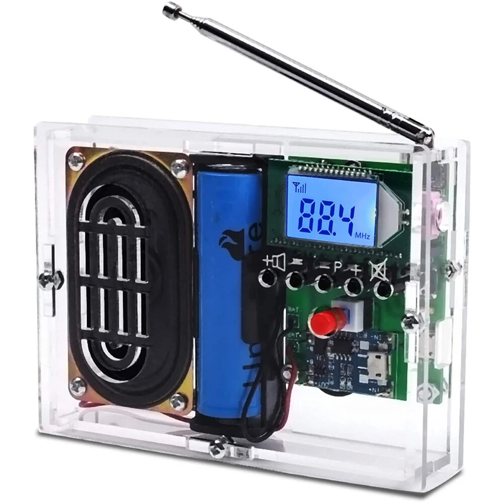
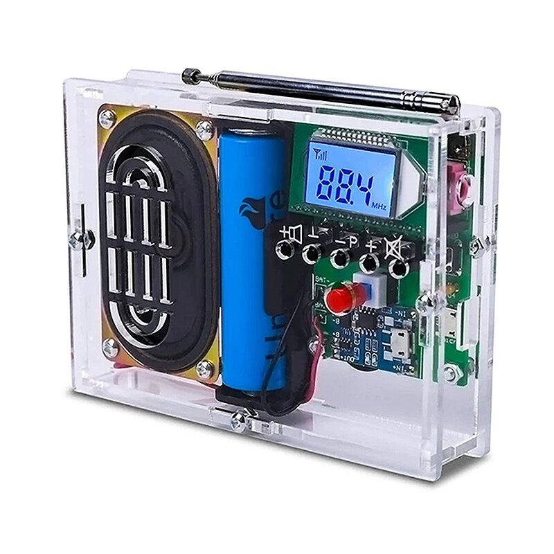
It is an 76.0MHz-108.0MHz Wireless FM Radio Receiver DIY Kit. It has a built-in high-definition display LCD display screen which can clearly display the receiving frequency and it can store 22 radio stations, which is enough to meet your needs.
Feature:
>>>Manual: Click here to open<<<
1. LCD Display FM Radio Receiver DIY Kit
2. Work Voltage: DC 3.0V~5.0V
3. Output impedance: 8ohm
4. Output power: 5W
5. Output channel: Mono for speaker and Dual channel for earphone
5. Frequency: 87.0MHz~108.0MHz (Disable CampussBroadcasting Band)
6. Frequency:76.0MHz~108.0MHz (Enable CampussBroadcasting Band)
7. Equivalent noise: >=30dB
8. Automatically search for radio stations
9. Built-in 30-level digital volume adjustment
10. Automatic memory function after power off
11. Built-in rechargeable module
12. Power saving mode with backlight off for 20 seconds
13. Support speaker and earphone audio output
Use Methods:
1. Keep press AUTO button to automatically search and store the radio stations that can be listened to.
2. Automatically name searchable stations like P01,P02,P02 and so on.
3. Press P+ and P- to switch saved stations.
4. Press V+ and V- to adjust volume from V00 to V30.
5. Switch CampusBroadcasting Band: Keep press V+ and V- before power ON and then turn ON work power switch. It means enable CampusBroadcasting Band if display C1 on LCD. It means disable CampusBroadcasting Band if display C0 on LCD.Available after restart.
6. Enable backlight mode: Keep press P+ and P- before power ON and then turn ON work power switch. It means keep backlight ON if display B1 on LCD. It means the backlight will turn OFF after 20second if display B0 on LCD(This is the power saving mode).Available after restart.
7. It can output audio from speaker and earphone jack. The speaker of the module does not work when the earphone is connected.
Note:
1. It cannot receive radio while it is charging.
2. It is a wireless module. So do not use it in an environment with siggnal interference.
3. Input charging voltage form micro USB on the bigger PCB.
Installation Tips:
1. User needs to prepare the welding tool at first.
2. Please be patient until the installation is complete.
3. The package is DIY kit. It need finish install by user.
4. The soldering iron can"t touch the components for a long time(1.0 second), otherwise it will damage the components.
5. Pay attention to the positive and negative of the components.
6. Strictly prohibit short circuit.
7. User must install the LED according to the specified rules. Otherwise some LED will not light.
8. Install complex components preferentially.
9. Make sure all components are in right direction and right place.
10. It is strongly recommended to read the installation manual before starting installation!!!
11. Please wear anti-static gloves or anti-static wristbands when installing electronic components.
Installation Steps (Please be patient install!!!):
Step 1: Install 1pc 39Kohm Metal Film Resistor at R1.
Step 2: Install 2pcs 10Kohm Metal Film Resistor at R2,R3.
Step 3: Install 1pc SOP-16 IC LM4863 at U1.There is a mark on one end of the IC and there is a mark on PCB where the IC can place on.These two marks are corresponding to each other and are used to specify the installation direction of the IC Socket.
Step 4: Install 1pc micro USB socket at J2.
Step 5: Prepare 6pcs pin header.
Step 6: Install 1pc Charging Module at J7 and fix by 6pcs pin header.
Step 7: Remove black fixed block from 6pcs pin header and fix Charging Module.
Step 8: Install 1pc 0.1uF Monolithic Capacitor at C2.
Step 9: Install 1pc 1uF 50V Electrolytic Capacitor at C1.Pay attention to distinguish between positive and negative.The Longer pin is positive pole.
Step 10: Install 1pc 3.5mm Audio Socket at J5.
Step 11: Cut a pin from 16Pin Female Socket.
Step 12: Install Female Socket at FM.Pay attention to the direction of the cut pin.
Step 13: Install 1pc Self-locking Button at S6.
Step 14: Install 5pcs 6*6*20mm Black Button at S1-S5.
Step 15: Install 1pc Self-locking Button Cap on Self-locking Button.
Step 16: Install 1pc Antenna at ANT.Note that the antenna should be installed on the front of the PCB.
Step 17: Install 1pc 18650 Battery Box at J1,J3.Pay attention to the positive and negative.Red wire is positive pole.
Step 18: Install 2pcs 15cm black Cable on speaker.
Step 19: Connect speaker to PCB at SP. The speaker does not distinguish between positive and negative.
Step 20: Install 1pc FM Audio Receiver on Female pins.Pay attention to the direction of the cut pin.
Step 21: Tear off the protective film on the surface of the acrylic shell.
Step 22: Install 4pcs M3*15mm Copper Pillar and 4pcs M3*10mm Screw on Acrylic bottom plate.
Step 23: Fixed speaker on acrylic bottom plate by 4pcs M3*6mm Screw.
Step 24: Install 3pcs M3*6mm Screw and 3pcs M3 Nut on Acrylic bottom plate.Note that the wire should not be placed between the PCB and the acrylic.
Step 25: Fixed main PCB on acrylic bottom plate by 3pcs M3 Nut.Note that the wire should not be placed between the PCB and the acrylic.
Step 26: Adjust the position of the battery box. Do not place the wires under the battery box. The wires can be moved to both ends of the battery box.
Step 27: Fix other acrylic plate by 6pcs M3*6mm Screw and 6pcs M3 Nut.
Step 28: Connect to power supply and enjoy the effect.
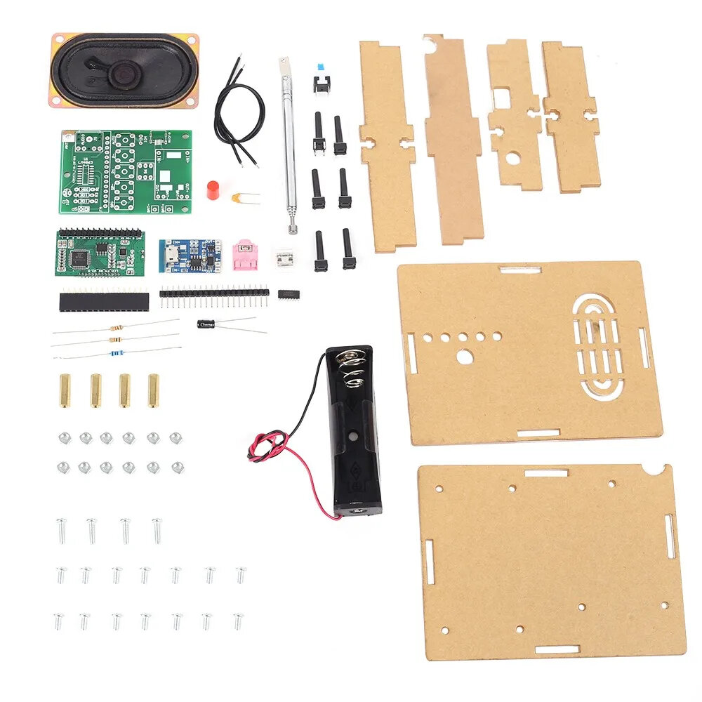
| No. | Component Name | PCB Marker | Parameter | Quantity |
| 1 | LM4863 | R7 | SOP-14 | 1 |
| 2 | 3.5mm Audio Socket | R1,R2.R4,R5,R8~R14 | 5Pin | 1 |
| 3 | Monolithic Capacitor | R3 | 0.1UF 104 | 1 |
| 4 | Electrolytic Capacitor | Y1 | 1uF 50V | 1 |
| 5 | Metal Film Resistor | C1,C2 | 10K ohm | 2 |
| 6 | Metal Film Resistor | TEA5767 | 39K ohm | 1 |
| 7 | FM Audio Receiver | LM386 | 41*22mm | 1 |
| 8 | Black Button | U1 | 6*6*20mm | 5 |
| 9 | Micro USB Socket | R6 | SMD | 1 |
| 10 | Antenna | C4,C5,C6 | 80mm-255mm | 1 |
| 11 | Female Pin | C3,C9,C11 | 16Pin | 1 |
| 12 | Self-locking Button | C7,C8 | 8*8mm | 1 |
| 13 | Self-locking Button Cap | Q1-Q4 | Red | 1 |
| 14 | 18650 Battery Box | 5V | 1 | |
| 15 | Male Pin | D13 | 7Pin | 1 |
| 16 | Charging Module | 056SMC_4 | 26*18mm | 1 |
| 17 | Cable | S4 | 15cm | 2 |
| 18 | Speaker | S4 | 8ohm 5W | 1 |
| 19 | Acrylic Shell | S1,S2 | 6 | |
| 20 | Copper Pillar | LM386 | M3*15mm | 4 |
| 21 | Screw | U1 | M3*10mm | 4 |
| 22 | Screw | X1 | M3*6mm | 14 |
| 23 | Nut | M3 | 12 | |
| 24 | PCB | SP | 1 |
Package Include:
1x LM4863
1x 3.5mm Audio Socket
1x Monolithic Capacitor
1x Electrolytic Capacitor
2x Metal Film Resistor(10Ku03a9)
1x Metal Fim Resistor(39Ku03a9)
1x FM Audio Receiver
5x Black Buttons
1x Micro USB Socket
1x Antenna
1x Female Pin
1x Self-locking Button
1x Self-locking Button Cap
1x 18650 Battery Box
1x Male Pin
1x Charging Module
2x Cables
1x Speaker
6x Acrylic Shells
4x Copper Pillars
4x Screws(M3*10mm)
14x Screws(M3*6mm)
12x Nuts
1x PCB


